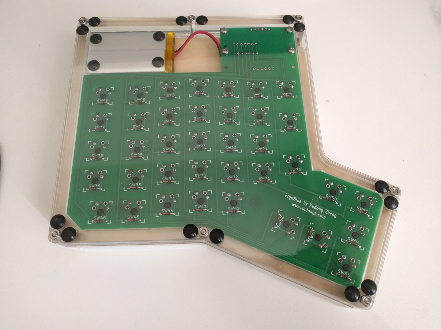
Diodes are necessary for the keyboard matrix scanning process to work. I have them beneath the PCB, on the opposite side of the switches. The solder joints are therefore above the PCB, on the same side as the switches. This made sense given the 0.22" thickness of my plate. You can also put the diodes above the PCB if you want.
The black cathode should face the side of the thumb cluster and the micro processor and the red anode is on the side of the battery. See this photo if you are confused about the orientation.
Soldering the switches for the ErgoBlue is no different from soldering switches for the ErgoDox or any other mechanical keyboard. There are lots of YouTube videos of people soldering switches or soldering in general.
The side of the microprocessor with the Micro USB port should face the side of the thumb cluster. You can use M2.5 screws to further strengthen the connection between the main PCB and the microprocessor board.
The mounted stabilizer clips will be a tight fit in the keyboard plate. Giving them additional space will make them pop out more easily.
There may be some friction between the stabilizer inserts (that go into the keycaps) and the stabilizer clips that prevents the stabilizer keys from popping up smoothly. I encountered this issue myself and the issue still exists in the case template. One way of solving this is by slightly adjusting the location of the stabilizer slots in the plate, though that is difficult to do and requires lots of trial and error. I simply used a wire cutter to slightly trim the stabilizer inserts. I cut a little on the side that was causing friction with the mounted stabilizer clips.