Two factors affect the location of the charging port: whether you use headers for Adafruit nRF52832 board and whether you mount it upside down. If you use headers between the PCB and the Adafruit nRF52832 board, obviously the Micro USB port will be higher up and you will need to adjust the layer of the charging port accordingly.
If you mount the Adafruit nRF52832 board upside down like I did, the "Left" layer under "Layer 34" should be used for the right side and vice versa. Mounting the board upside down allows you to use headers for easy desoldering without having to increase the height of the keyboard.
You can combine multiple layers onto a single document and run them together on the laser cutter to save time and money. You need to adjust the document for use with the specific laser cutter such as by changing the line colors, the line width, and so on. The steps should be obvious if you have previously used the laser cutter. If you are using an online service such as Ponoko, their support staff can double check your files and make sure you are doing things correctly.
I used the laser cutter (and 3D printer) at my school (JHU Makerspace), which significantly reduced the amount of development time and the total cost. If you are a student, you should look into whether your institution has a hacker/maker space with such tools. Many cities also have non profit hacker/maker organizations or public libraries with these equipment. You should search "'city name' hacker space" to get an idea of resources that might be available to you.
I tried making the case out of both acrylic and plywood. In my extremely limited laser cutting experience, acrylic was much easier to work with since plywood sheets may not be completely flat. Clear acrylic is pretty easy to find in your typical Home Depot or Lowe's, whereas you will need to find a specialty store such as Canal Plastics Center in NYC if you want something fancier. You can also find acrylic and plywood sheets on your typical e-commerce site (Amazon, eBay, etc).
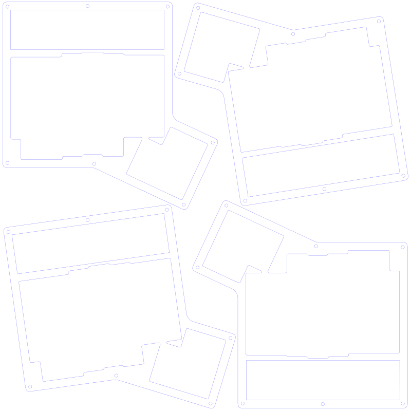
When using Ponoko, you can fit 4 layers onto one of their P2 sheets measuring 15.1" by 15.1". You will need to do some rotating for it all to fit. You can see an example below. If you using cutting wood, the rotation will result in the direction of the grain being inconsistent across the 4 layers.
When using plywood, experts recommend adding a finish to give it a more professional look and to protect it from environmental factors such as moisture. I used a water-based polyurethane semi-gloss finish from MinWax. There are lots of options that are beyond the scope of this blog post.
The SVG file can also be used for 3D printing though some minor modification may be necessary to help the software determine the parts that are "inside" or "outside". TinkerCAD is a free tool that can take the SVG file and output an STL for 3D printers. Obviously you must do some calculations and give each layer enough height so the components fit.
When 3D printing, you can combine multiple layers to save time. For example, layers 1 and 2 can go together, and so can layers 4 and 5. Layer 3 can also be printed with layers 4 and 5, though I would do it separately since layer 3 cannot be replaced without desoldering all the switches from the PCB. All the other cases are easily swappable. If you do decide to print multiple layers together, you need to pay extra attention and make sure that the charging port is in the correct location.