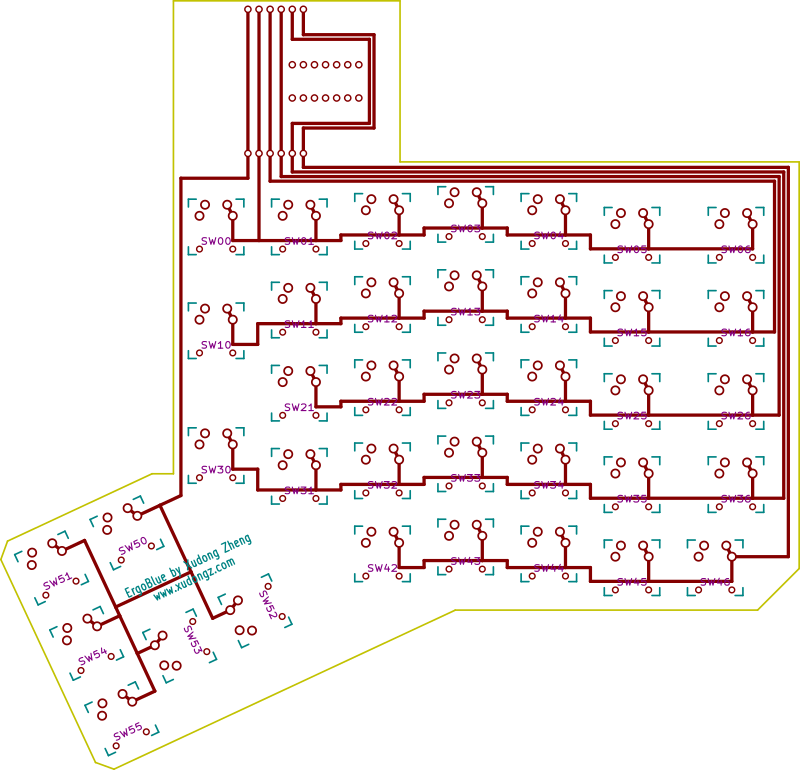
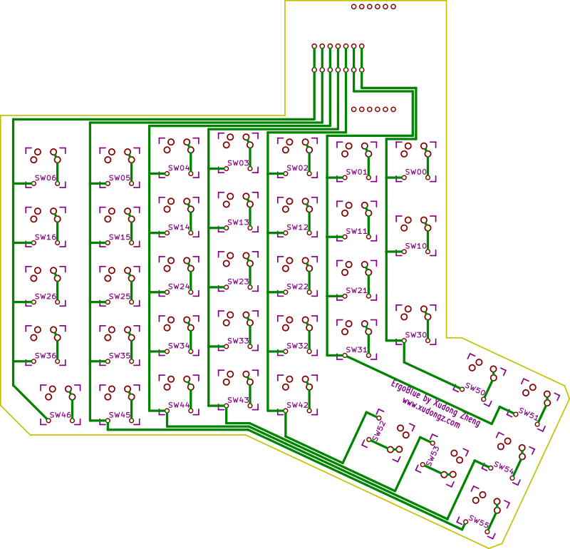
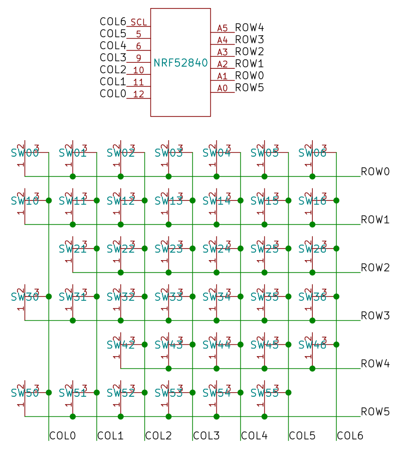
On the Adafruit nRF52840 board, the rows use pins A1, A2, A3, A4, A5, and A0. The columns use pins 12, 11, 10, 9, 6, 5, and SCL. The column pins are slightly different on the Adafruit nRF52832 board. The PCBs has been tested with both the Adafruit nRF52832 board and the Adafruit nRF52840 board. It is also possible to use the Nordic nRF52840 Dongle though an additional PCB is required1. The PCBs are available for sale but hand wiring is also a practical alternative.
Regardless of whether you purchase a PCB or hand wiring, you will need 1N4148 diodes. The PCB only expects the through hole version and does not support surface mount version.
Below you will find the circuit board design, which should give you an idea of how to hand wire. When using the PCB, you do not need to worry about most of this. One way to slightly simplify hand wiring is to take advantage of the diode legs and use them to connect the columns instead of using an additional wire. You will still need a wire for each row.
I designed an adapter PCB that bridges the layout of the Nordic nRF52840 Dongle with the Adafruit Feather layout that the main PCB expects. Switching from one to the other should only require desoldering the Adafruit board and soldering the adapter with the Nordic nRF52840 Dongle. On the software side, I've written enough code to demonstrate that it will work but a lot of parts are still missing. If you are interested in getting it to work, feel free reach out to me via email (address available on my homepage). ↩