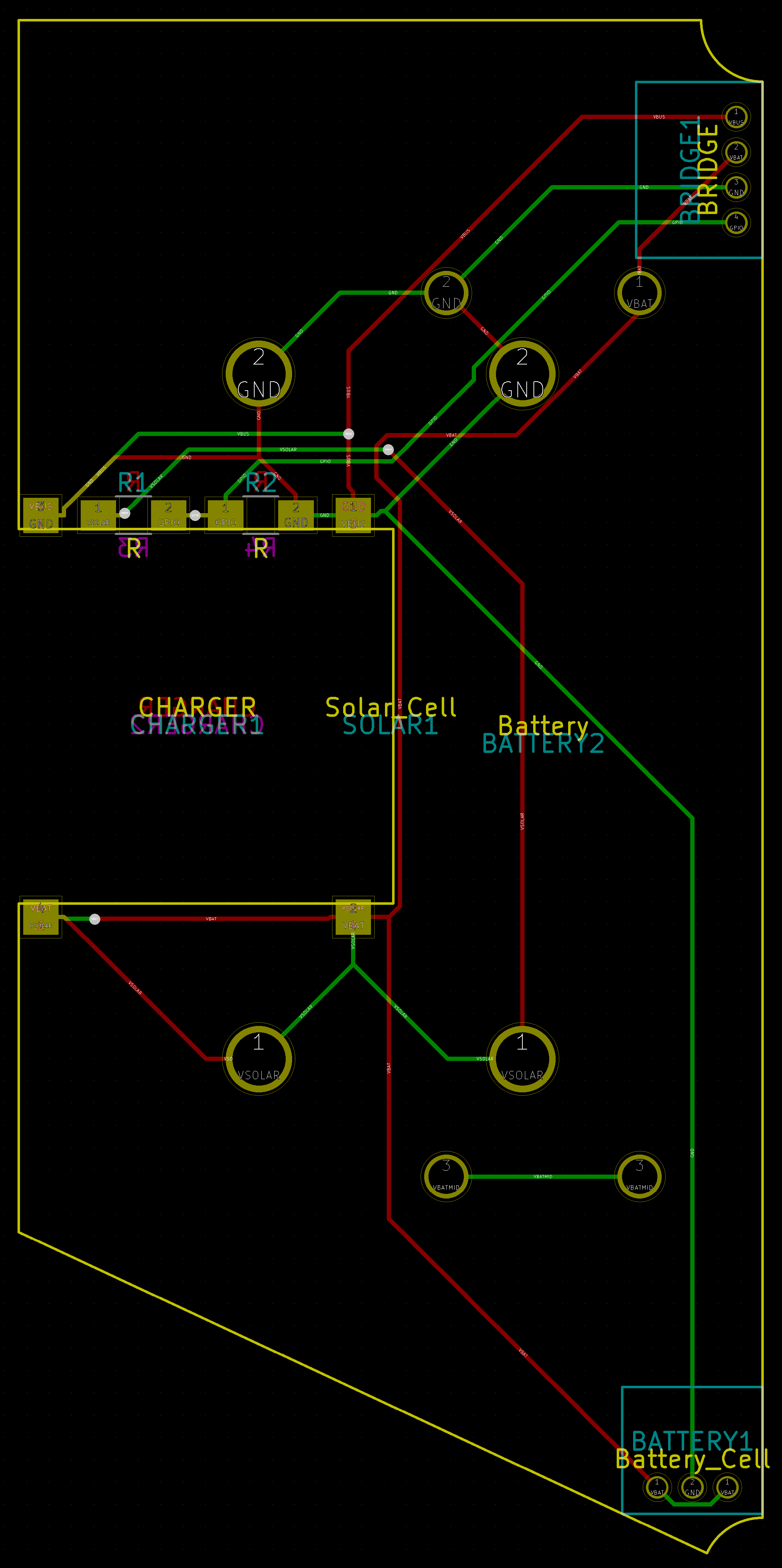
The solar PCB sits flush against the top of the case and holds the solar panels. When assembling, you may want to reference the PCB layout.
The ErgoBlue 2 uses a TI BQ25504 to charge the rechargeable batteries using energy from solar panels.
Each IXYS SM141K04LV can provide up to a theoretical 123mW of power. Each keyboard half has two such solar panels.
The battery JST connector has 3 pins rather than 2. The three pins are VBAT (side), GND (middle), and VBAT (side). Using 3 pins allows the connector to accommodate a variety of different batteries as the placement of the battery GND and VBAT wires varies from manufacturer to manufacturer.
Having a 3 pin female connector for a 2 pin male connector also obliges the users to look at the documentation and not plug in the battery blindly. This reduces the likelihood that the user will plug the battery in the wrong orientation and fry the electronic components.
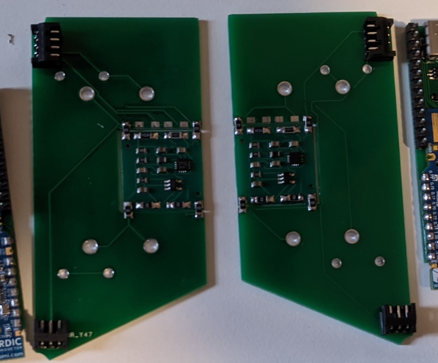
The charging circuit is on a separate PCB to simplify the manufacturing process. Four 0Ohm jumpers are used to connect the charger PCB to the solar PCB. The charger PCB should be installed such that all the components face down (the solar panels face up for comparison). When soldering the jumpers, the charger PCB should be oriented such that the 5 pin component is in the lower right hand corner.
The TI BQ25504 on the charger PCB uses a resistor divider network to configure the battery charging voltage.
You can use different resistor values if you want solar charging to stop at a different voltage. If you wanted exactly 4.2V for example, you'd use ROV1 = 4.464MOhm and ROV2 = 5.536MOhm. However given the availability and accuracy of resistors in the MOhm range, it makes sense to aim for a voltage slightly lower than the maximum allowed voltage.
If you want to configure the solar charger for a different voltage, use TI's SLUC484 spreadsheet.
To enable LiPoly charging over USB, RVBUS1 and RVBAT1 should be populated on the charger PCB with a 0Ohm jumper. USB charging must not be enabled if using 2 AAA batteries as the USB charging voltage is not configurable; the TP4054 charges to a fixed 4.2V with some margin of error.